Showing posts with label Blog. Show all posts

Friday, 15 March 2013

LPC800-MAX for Arduino users: not all sweetness and light!

A few days ago we received our prototype LPC800-MAX direct from NXP.  Top marks to NXP for getting it to us, and I was quite excited about the possibilities that it would offer.  Of course, I wanted to get all our example code, using the CrossWorks Platform API, running on the board.


Initial excitement quickly turned to disappointment.  Although the LPC800-MAX board is advertised as Arduino compatible, it leaves you with rather a lot of problems if you want to use shields with it.  Let's go through the limitations now.

Missing pins

Well, first off, consulting the schematic to provide a pad to connector mapping for the API, I discovered that Arduino D5 and D6 are not connected to any LPC800 pin!  What does this mean?  Well, it means that a number of readily-available shields, including nearly all LCD shields, are not immediately controllable with the LPC800-MAX.  Add to that things like the SparkFun El Escudo, Spectrum Shield, the ModKit Modproto shield, and all the 16x2 LCD shields just for starters!

Of course, do some cut-and-shut surgery on your shield connections or use a Go-Between Shield to make your connections, but still, you're missing something a lowly AVR provides.

So, you're going to be a little disappointed if you've already invested in some shields.  The good news is that the SolderCore LCD and Arcade shields don't require D5 or D6, so they just work with the LPC800-MAX.

More shield woe!

It doesn't stop there.  The default for Arduino D2 is that it's unconnected as well. You can rescue the situation by moving the position of SJ2 to connect TARGET_TX-PIO0_6 to PIO0_6 and, in doing so, connect up D2. I'm beginning to think this isn't such a great advertisement for Arduino compatibility.

Analog, not digital

Now, the analog header is for analog input. And indeed, it has four analog inputs routed to an I2C ADC/DAC.  You can't use those for digital output, which means that your "compatible shield list" reduces even further.  Strike LCD touch shields, BlinkM breakout, liquidware InputShield, IteadStudio Colors Shield...  You get the picture.

Getting it to work...

Although there are serious deficiencies with the LPC800-MAX for Arduino users, it still has I2C and SPI routed to the headers, and they work. So, you can connect some digital sensors and some SPI-based LCDs to do serious work. And it also has a built-in CMSIS-DAP which works with development tools such as CrossWorks.

I got the LPC800-MAX up and running in no time, despite the Arduino pin headaches. But if you've invested in Arduino shields, the Freedom-KL25Z board has a better set of features and more pins to play with, and has more RAM and flash.  Sure, it doesn't have LPCXpresso/mbed format to its name, and if that's what you're wanting, perhaps the LPC800-MAX has its place.

Sunday, 3 February 2013

Quadshot progress

Today I went into the office to sort out the remainder of the electronics that have been piling up on my desk and also taking over the nearby storage surface. That took some time, sifting through the bits and pieces and putting them back where they should be.

Anyway, progress continues on the Quadshot:


I ordered the Cappuccino variant form the original Kickstarter funding which delivered the airframe, but it means I must add my own flight hardware and software.  This is what I want to do because, although I'd like to fly it, what really interests me is the software that is needed to fly it.  The hardware is already done, I have a SolderCore and the CoreMPU.  For those unfamiliar with the CoreMPU, it's a small unit containing an MPU-6050 and an HMC5883L which is a 9DOF sensor array: accelerometer, gyroscopes, and magnetometer. In addition, I have a CorePressure module that can accurately measure altitude using barometric pressure so, hopefully, a programmed controlled landing on autopilot will be possible!

Saturday, 2 February 2013

Writing a gyro driver for CoreBASIC

Today I'm in the office, tidying up source code to release to the world as a package.  The package is so that you can use all those drivers you'd find in CoreBASIC, but from C.  This is taking quite some time: writing the code is the easy bit, but writing the API documentation for users is hard.  I thought that I had done a good job of it when constructing all the CoreBASIC and CrossWorks Device Library code, but reviewing it, it just isn't up to scratch.

As part of this task, I thought I'd share how I typically develop a driver for inclusion in CoreBASIC.  Today, I'm constructing a driver for the L3G4200D MEMS gyroscope from STMicroelectronics.  I've had a couple of breakout boards from SparkFun for a while now, and I ordered two.

First things first...

One of the first things that I do is wire up the breakout board to test it out.  Historically, I hand-wired the boards to the SolderCore directly, but this is both time consuming and error prone.  When I change my software, I want to be able to test that I haven't broken anything by quickly grabbing a module from our extensive library of hardware, plug it in, and go!  Finding all the data on the chip, the breakout, and having prototyping wires srouting from boards takes much too much time.

Instead, what I do now is use a CoreProto board and attach the breakout to it.  Here's what I'll be snapping together:


I place the module on the CoreProto and wire-wrap it.  My soldering and wire-wrapping skills are not the best, and I try to remove the flux with a cleaner, but to be honest, it's not my day job.  This is what I end up with:


Once I've constructed that, I plug into into a SenseCore, which is installed on top of a SolderCore.  Now I have a great sensor platform! Whenever I want to whip up a demonstration, or make sure that the latest modifications to the software haven't impacted the existing drivers, all I need to do is take a SolderCore, a SenseCore, and plug in the SExI-format module and I'm good!

This is what it looks like:


So now I am ready to try some software.

First connection

I have my hardware set up, so I need to see if the module is responding.  To do this, the easiest thing is to use CoreBASIC interactively and poke the sensor.  It's much faster to do this than construct a program in C, compile it, fix errors, download it, and debug why the blazes it's not working!  As CoreBASIC already has full support for I2C and SPI, you have a great test platform at your fingertips, so why use something more fiddly and less immediate?

Reading the L3G4200D datasheet, there's a "Who am I" register at address 0x0F that should read back 0xD3.  So, fire up CoreBASIC and try it:


Great!  The sensor is working.  I can communicate with it.  From there on, I can play with the registers from the datasheet in CoreBASIC and make sure I understand what I am seeing.

Write it in C...

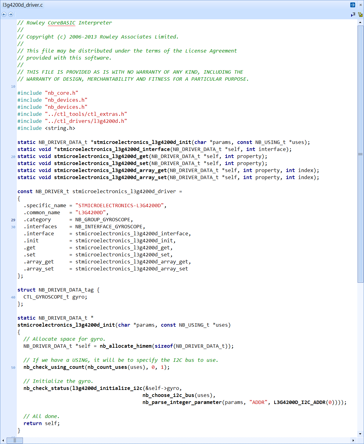
From there, it's a short distance to write the code in C and integrate it into the set of confidence tests.  I write the driver in C and use CrossWorks to compile it into the CrossWorks Device Library:


The I write the confidence tests to ensure that I can communicate and demonstrate that it works as I expect:

 
Running this project, I can see the output change when I spin the sensor:


So, now I have the sensor working in C.  What I need to do now is construct the CoreBASIC interface onto this sensor, which is pretty much gruntwork because the hard work is already done:


Drum roll please...

And now, of course, it's available in CoreBASIC!


How easy is that to read a gyro?  A CoreBASIC user can do it, interactively, in just two lines.  No C compiler, no compilation, nothing. Immediate.

Statistics

So, here are some vital statistics for this task.  The whole exercise took about four hours to integrate the sensor: from making the SExI module to firing up CoreBASIC and printing the gyro readings.

The low-level driver code, confidence tests, and CoreBASIC integration is about 500 lines of code, but that does not include all the framework functions such as I2C drivers, gain and bias application, bus selection, and so on, as that is already written.

However, with all that code written, it immediately works on all implementations of CoreBASIC (SolderCore, Freedom Board, Raspberry Pi) and on all C platform targets that we support.  Great!

Monday, 28 January 2013

Twittering and signatures

One of the things that I want to be able to do at some point is connect to a server using a secure socket.  That's a little way off yet, but isn't so distant that I can put it out of my mind.

Many Internet-of-Things devices might want to connect securely; and more than that, robust authentication is also necessary.  Simple authentication is being discarded and OAuth is starting to become the norm for services such as Twitter and COSM.

In view of that, I constructed an example a little while ago that will sign a Twitter API call using an HMAC-SHA1 signature.  Rowley Associates has an established history in all this crypto boffinry as we wrote compilers under contract to Microsoft for their smart card virtual machine, and we also wrote the SmartWorks for MULTOS product which was bought out, rebranded, and now rests with MAOSCO as SmartDeck.  This signing code isn't hardcore crypto: it's rather simple, in fact.

So, if you're interested in the signing code, you'll find it here:

http://www.soldercore.com/manual/corebasic_twitter_oauth_signature.htm

This example takes the example from Twitter of constructing an OAuth signature and codes it up in CoreBASIC.  When I run the program, I get the correct signature:


So, we're on the way to direct posting to Twitter without using a proxy application!